A while ago I came across Dalibor Farny who taught himself to build Nixie tubes. To my knowledge he is the only one still building Nixie tubes. If you are interested, he also uploaded an interesting video how he builds them.
After seeing his tubes, I had the idea to build a shot timer for my espresso machine. It might sound esoteric, but the shot duration is an important parameter when pulling shots. As shots usually take about 25 seconds, I am good to go with two Nixie tubes which can display up to 99 seconds.

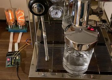
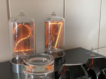
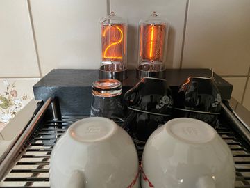
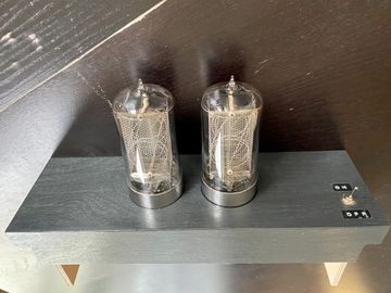
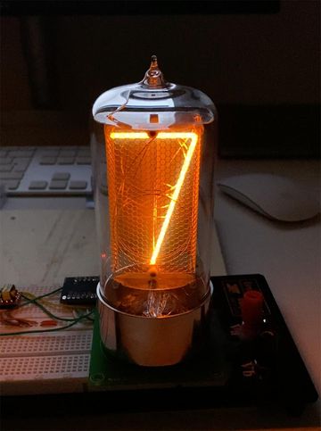
The result
Here is a video and some pictures of the final result.


The build
The two main challenges I faced were
- Detecting whether the pump runs, so I know when to start and stop counting
- Switching 170V on 20 anodes, 10 per nixie tube
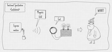
As I have been working on this for fun, I figured this should be over-engineered, so I wanted to see whether I can detect the magnetic field of the pump to know whether a shot is prepared or not. Also, this would mean I won't need to alter the espresso machine, kind of the minimal invasive approach, which also had it charm.
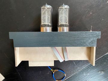
To top everything off, a close friend helped me with his knowledge and workshop to build a nice housing. Thanks again Nils!
Detecting the magnetic field
My first idea was to use a magnetometer used in smartphones as compass sensor. I have tried the two ICs MAG3110 and QMC5883. Unfortunately both oversample and have no option to get a raw signal. I was able to see a change in magnitude, but further processing of the signal did not feel possible. Therefore, the only option going forward with one of these two seemed to be to threshold the value. This felt like I could do better.
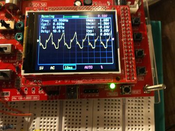
So I decided to get the electric screwdriver out and start my own antenna/coil production, without having any actual idea what I am doing. Nevertheless, hooking it up to an amplifier and oscilloscope looked promising. The signal shows a peak at 50Hz, which seemed pretty plausible.

After this success I started sampling values and ran a fourier transformation on it and plotted the results.

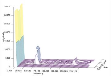
The pump is switched on between 15 and 5 (time, of some unknown unit). Of course the plot has an off-by-one error, the peak is actually at 50Hz, not 53.125Hz. Also we see smaller peaks at multiples of 50Hz.
To actually decide whether we need to count or not, I wanted to fit a known frequency spectrum to the measured one, calculate the quadratic error, yada yada. Turned out that worked really badly. Super reliable in contrast works simply thresholding 50Hz. Now I am using an Arduino nano which is constantly sampling, calculating the FFT and thresholding 50Hz to know whether it should better start counting or not.
Controlling two Nixies
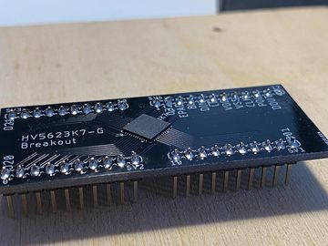
To keep the footprint small and because it felt more elegant, I wanted to use an IC to switch the Nixies instead of using 20 transistors. I found the HV5623 which is a 32 bit shift register, able to sink 32 times 220V. This is more than enough for my application, as I have 2x 10 cathodes with 170V that need to be sunk. As this chip is only available in super tiny packaging and, to me, seems impossible to solder by hand, I created and ordered an assembled breakout board.

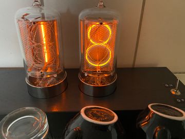
Here is a video of the first time controlling one tube with the breakout board. I had an error in the tube socket, as I designed the traces too close together which short-circuited the digits 8 and 9, therefore they light up together.
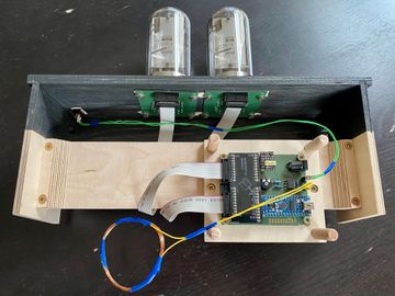
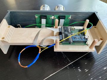
The electronics
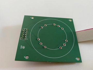
The pcb and socket for the tubes:

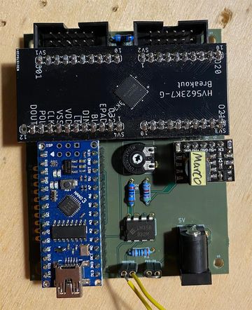

As customs had a nice (tax-wise) surprise with the breakout board, I did not want to order again from China. Also, PCB assembly seems crazy expensive in Europe, so I decided to not create a final pcb combining all of these elements but instead reuse the breakout board and everything else I already had on the prototyping board. Therefore, I designed a PCB which more or less resembles the circuitry on the breadboard.
The final pcb consists of these parts:
- An Arduino nano
- A 5V to 170V step-up converter, bought on eBay
- A breakout board for the HV5623 to control the nixies
- An op-amp based on the LM358 to amplify the current the magnetic field induces
Here is a video of testing the electronics